Day 7: In-depth Analysis of Navigation Data
Lecturer: Dr. Andrew, Senior Researcher, Navigation Systems Laboratory
Date: March 2003
Topic: From Errors to Accuracy – Analysis and Integrity Control of the Navigation Field
1. Introduction: Why Trust but Verify Navigation Data?
Modern navigation systems have firmly entered our lives, providing precise positioning for a variety of tasks. However, relying on GNSS-measured data without verification is not acceptable. Navigation accuracy is affected by various errors:
- Atmospheric disturbances: the ionosphere and troposphere distort radio signals, causing delays and errors.
- Time inaccuracies: even atomic clocks on satellites and receivers have microscopic deviations.
- Satellite geometry: the arrangement of satellites affects measurement accuracy.
- Hardware and software failures: satellites and receivers may malfunction.
Simple analogy: Imagine a choir where each voice is a signal from a satellite. For "harmonious sounding" (accurate navigation), all "voices" must be clean. Erroneous data are "off-key notes" that need to be identified and corrected.
Purpose of the lecture: the study of GNSS data analysis and integrity control for:
- ✅ Improving the accuracy of navigation
- ✅ Ensuring reliability of navigation information
- ✅ Detecting and excluding failures in the data
Key analysis tasks:
- ✅ Assessment of differential corrections to compensate for errors
- ✅ Validation of signal reliability to evaluate their quality
- ✅ Exclusion of erroneous data to improve accuracy
2. Assessment of Differential Corrections: Eliminating Common Errors
2.1. What Are Differential Corrections and How Do They Work?
Differential corrections are a method of improving GNSS accuracy using a base station with known coordinates.
Operating principle: The base station compares the measured and the actual distances to satellites. The difference is the differential correction. Corrections are transmitted to the rover to compensate for common errors.
Differential GPS (DGPS) Key Components
- 1. GPS satellites
- Constellation of satellites transmitting navigation signals
- 2. Reference Station
- Stationary ground station with precisely known coordinates that calculates correction data
- 3. Mobile Receiver
- Receiver on moving object (aircraft, vehicle) that applies corrections for improved accuracy
- 4. Differential Correction Signal
- Adjustments computed by reference station and sent to mobile receivers
- 5. Communication Link
- LF/MF radio or other means of transmitting corrections from base to rover
Formula for the differential correction (for pseudorange):
Formula breakdown:
-
\(R_{i,j,k}\) – true geometric distance from station \(i\) to satellite \(j\):
\[R_{i,j,k} = \sqrt{(x_{j,i,k} - X_i)^2 + (y_{j,i,k} - Y_i)^2 + (z_{j,i,k} - Z_i)^2}\]
- \(S_{i,j,k,3}\) – measured pseudorange (after atmospheric corrections)
- \(k\) – GLONASS coefficient (1 for GLONASS, 0 for others)
- \(c\) – speed of light
- \(\Delta\tau_{\text{GLONASS}}\) – GLONASS time correction
Index explanations:
- \(i\) – base station number
- \(j\) – satellite number
- \(k\) – time moment
Numerical example of calculating a differential correction:
Suppose:
- Measured pseudorange: \(S_{i,j,k,3} = 20,000,150\) m
- Geometric distance: \(R_{i,j,k} = 20,000,000\) m
- GLONASS time correction: \(k \cdot c \cdot \Delta\tau_{\text{GLONASS}} = 50\) m
Differential correction:
2.2. Taking Measurement Speed into Account: Pseudovelocity
To improve accuracy, pseudovelocity – the rate of change of the pseudorange – is analyzed. Differential corrections for pseudovelocity:
where:
Important: Discrepancies between measured and calculated velocities indicate errors.
3. Navigation Field Integrity Control: Detecting "Off-key Notes"
3.1. Reliability Matrices: \(H_i\) and \(G_i\)
Integrity control involves assessing the reliability of GNSS data. An analysis of the consistency of redundant measurements is used. Check matrices \(H_i\) (pseudorange) and \(G_i\) (pseudovelocity) are formed, reflecting the consistency of corrections between satellites. This consistency-checking approach belongs to the same family of techniques as Receiver Autonomous Integrity Monitoring (RAIM) — a publicly documented GNSS integrity-monitoring approach described in open literature in the late 1980s, including works by Brown & McBurney and Parkinson & Axelrad. RAIM-type methods are widely associated with civil GNSS integrity monitoring, especially in aviation safety contexts.
Algorithm for forming matrix \(H_i\):
For base station \(i\) and pairs of satellites \((j_m, j_n)\):
- Check data availability: Pseudorange data must be available for both satellites.
-
Calculate the difference of corrections:
\(\delta S_{m,n} = \left| \Delta \hat{S}_{i,j_m,k_m} - \Delta \hat{S}_{i,j_n,k_n} \right|\)
- Compare with threshold (DS): Threshold value (DS) sets the permissible difference of corrections. The choice of DS depends on the required accuracy and the noise level in measurements. In this example, we use DS = 20 meters. In real systems, DS can be set based on statistical error analysis and navigation integrity requirements.
-
Fill the matrix element:
\[\{ H_i \}_{m,n} = \begin{cases} 0, & \text{if data are available and } \delta S_{m,n} \leq DS \\ 1, & \text{otherwise} \end{cases}\]
Matrix \(G_i\) is formed similarly for pseudovelocity with threshold \(DS^{\dot{ }}\).
Example of forming matrix \(H_i\):
| Satellite pair | Difference of corrections (\(\delta S_{m,n}\)) | Comparison with threshold (DS=20 m) | Matrix element (\(\{ H_i \}_{m,n}\)) |
|---|---|---|---|
| \((j_1, j_2)\) | \(|-10 - (-15)| = 5\) m | \(5 \leq 20\) | 0 |
| \((j_1, j_3)\) | \(|-10 - 100| = 110\) m | \(110 > 20\) | 1 |
| \((j_2, j_3)\) | \(|-15 - 100| = 115\) m | \(115 > 20\) | 1 |
4. Decision-making on Failure: Summing "Voices of Dissent"
For each satellite \(j_n\), the system calculates the column sums of the reliability matrices \(H_i\) and \(G_i\):
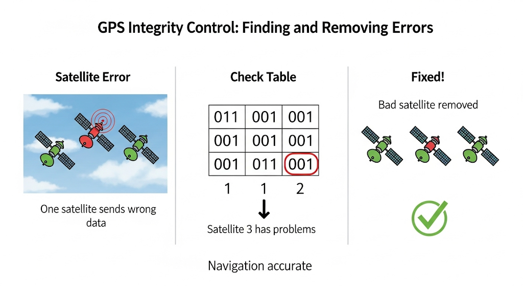
Interpretation of the sums: The higher the sum for a satellite \(j_n\), the higher the probability that this satellite is the source of an error or inconsistency. These sums indicate how many times the satellite \(j_n\) was "inconsistent" with others in the matrices \(H_i\) (for pseudorange) and \(G_i\) (for pseudovelocity).
Decision-making rule:
- Correct operation: If for all observed satellites both conditions \(\Sigma_{i,j_n}^{H} = 0\) and \(\Sigma_{i,j_n}^{G} = 0\) hold, then all satellites are considered operational, and the navigation field is deemed reliable.
- Detected errors: If at least one satellite \(j_n\) satisfies \(\Sigma_{i,j_n}^{H} \neq 0\) or \(\Sigma_{i,j_n}^{G} \neq 0\), then this satellite is considered suspicious and is excluded from further navigation calculations.
Example of Matrix Interpretation:
| Satellite | \(j_1\) | \(j_2\) | \(j_3\) | Column Sum \(\Sigma_{i,j_n}^{H}\) |
|---|---|---|---|---|
| \(j_1\) | - | 0 | 1 | 1 |
| \(j_2\) | 0 | - | 1 | 1 |
| \(j_3\) | 1 | 1 | - | 2 |
Analysis of Table Data:
- For satellite \(j_1\): \(\Sigma_{i,j_1}^{H} = 1\)
- For satellite \(j_2\): \(\Sigma_{i,j_2}^{H} = 1\)
- For satellite \(j_3\): \(\Sigma_{i,j_3}^{H} = 2\)
If the matrix \(G_i\) (not shown) has all zero sums (\(\Sigma_{i,j_n}^{G} = 0\)), then satellite \(j_3\) is the most likely to be erroneous and is excluded.
Integrity Control Algorithm:
- Start of the integrity control algorithm.
-
For each base station \(i\):
- Form the \(H_i\) matrix based on pseudorange corrections
- Form the \(G_i\) matrix based on pseudovelocity corrections
- Compute the column sums \(\Sigma_{i,j_n}^{H}\) and \(\Sigma_{i,j_n}^{G}\)
-
Decision-making:
- If all satellites satisfy \(\Sigma_{i,j_n}^{H} = 0\) and \(\Sigma_{i,j_n}^{G} = 0\), they are considered reliable
- If any satellite has a nonzero sum, it is marked as erroneous and excluded
- End of the integrity control algorithm. The final navigation solution is computed using only the remaining reliable satellites.
5. Final Conclusions: Achieving Accuracy through Analysis
- 📌 Differential corrections compensate for common errors, increasing accuracy
- 📌 Integrity control identifies erroneous data, ensuring reliability
- 📌 Reliability matrices objectively assess measurement quality
6. Questions for Students: Check Your Understanding
- Why is it impossible to rely on raw GNSS data without analysis?
- How does the atmosphere affect measurements, and how do corrections help?
- What other integrity control methods exist (e.g., RAIM)?
💬 Advice from Andrew: Be the quality controller in the satellite "choir"! Check each "voice" to achieve the "pure sound" of accurate navigation. "Trust, but verify!" Good luck!